K2600 6 pole#
A test that can be used for IV-characterization of a DUT by using up to 6 Keithley 2600 series SMUs in parallel.
Description#
The test is used for IV-characterization of a DUT by using up to 6 Keithley 2600 series SMUs in parallel. The test can be used for a wide range of applications, such as the characterization of transistors, diodes, or solar cells. Each SMU can be configured individually and offers many setting options. The measured values can be displayed in the diagram while the measurement is running. How exactly the test works is described under Test procedure.
Input parameters#
The input parameters are differentiated between parameters that apply to all SMUs (General parameters) and those that only apply to a specific SMU (SMU parameters).
General parameters:#
| Parameter | Description |
|---|---|
| NPLC | The number of power line cycles (NPLC) (see NPLC for details) |
| Hold time [s] | The settling time before a measurement is performed, which only applies to SMUs whose Operation is set to Step (see Test procedure for details) |
| Delay [s] | The settling time before a measurement is performed, which only applies to SMUs whose Operation is set to Sweep (see Test procedure for details) |
| Step points | Specifies the number of current or voltage increments for the outer step loop (see Test procedure for details) |
| Sweep points | Specifies the number of current or voltage increments for the inner sweep loop (see Test procedure for details) |
| Break on compliance | If enabled, the test will stop if more than 99% of the limit of the corresponding SMU is reached |
| Dual sweep | If enabled, the test will perform a dual sweep meaning that the sweep runs from the Start value to the Stop value and back to the Start value |
SMU parameters:#
| Parameter | Description |
|---|---|
| Device | The SMU, which is used for sourcing and measuring |
| Operation | The operation the SMU performs. Either Step, Sweep or Bias (see Test procedure for details) |
| Mode | The mode in which the SMU operates. Either Voltage for voltage source mode or Current for current source mode |
| Start [V/A] | The start level of the SMU (see Test procedure for details) |
| Stop [V/A] | The stop level of the SMU when Step or Sweep Operation is selected (see Test procedure for details) |
| Limit [A/V] | The limit of the current or voltage output depending on the Mode |
| Range | The range of the SMU. Either Auto (SMU auto ranges during operation) or Fixed (see Fixed range setting for details) |
| Four wire | Determines if 4-wire measurement is active (see 4 wire measurement for details) |
| Advanced -> Low range [A/V] | The lower range defines the lowest measure range used by the SMU when Range is set to Auto (see Low range for details) |
| Advanced -> Measure range active | Determines if the measure range should be set to the given value. If disabled, the measure range is set to the value of the Limit |
| Advanced -> Measure range [A/V] | The value that is set as measure range |
Further explanations#
Test procedure#
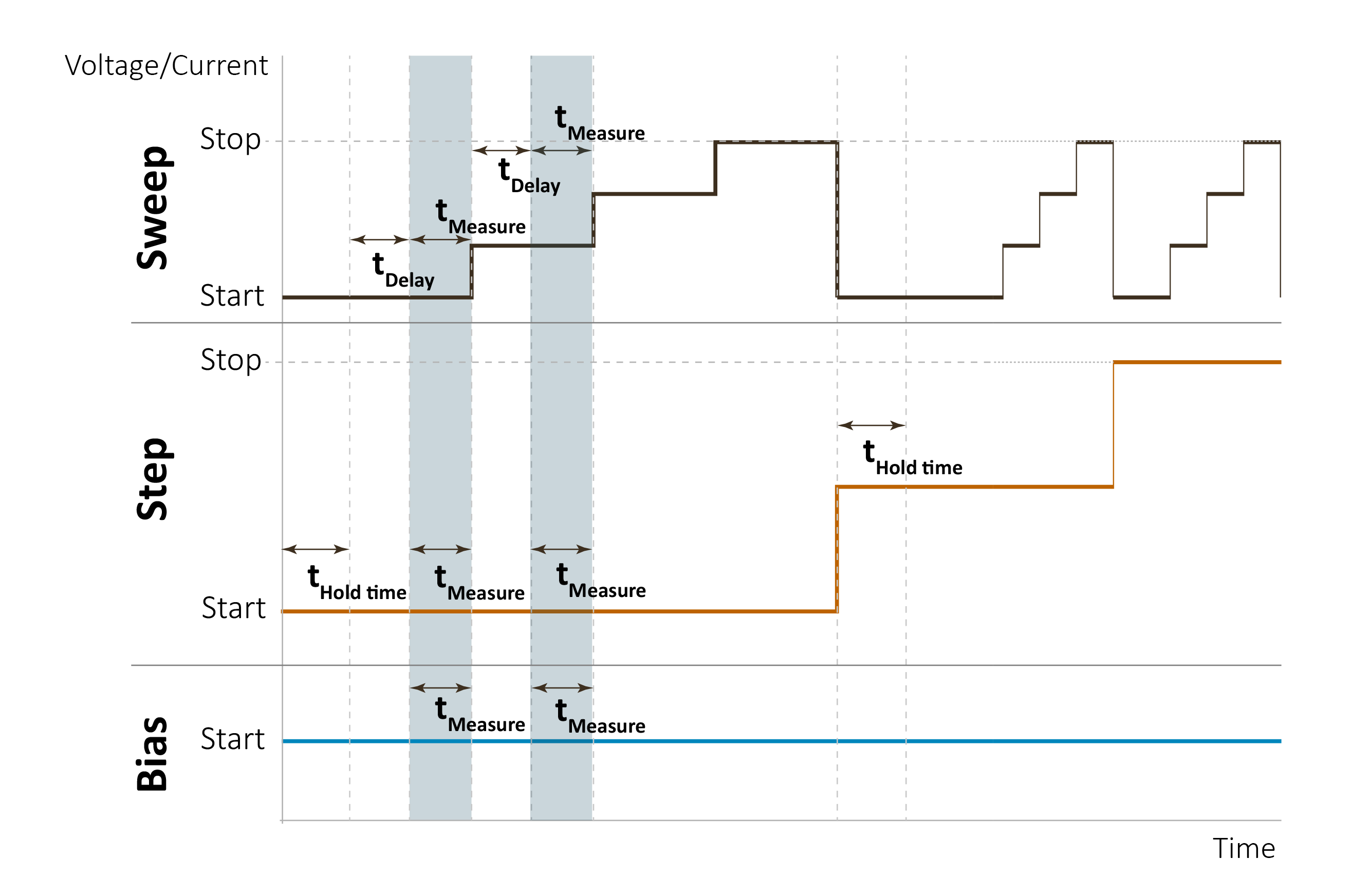
When the test is started the SMU performs as the Operation is configured:
Bias:
The SMU sets the output level to the Start value and leaves it at this level for the duration of the test.
Step:
The SMU starts at the Start value and increases the output level after a sweep was performed until the Stop value is reached. The step increment is determined by the Step points parameter and calculated as follows: \(\frac{Stop - Start}{\text{Step points} - 1}\). After the corresponding level is set to the SMU the test waits for the Hold time before a sweep is performed.
Sweep:
The SMU starts at the Start value and increases the output level until the Stop value is reached. The sweep increment is determined by the Sweep points parameter and calculated as follows: \(\frac{Stop - Start}{\text{Sweep points} - 1}\). After the corresponding level is set the test waits for the Delay before a measurement is performed.
The test performs a measurement for each SMU in parallel independently of the Operation. This means that every SMU starts the measurement at the same time. The next step or sweep is performed after all SMUs have finished the measurement.
See the following figure for a graphical representation of the test procedure:
NPLC#
The number of power line cycles (NPLC) indicates the duration for which an input signal is integrated to generate a single measurement where 1 PLC corresponds to 20 ms (1/50) for a 50 Hz power line frequency and 16.67 ms (1/60) for a 60 Hz power line frequency. The value can be set between 0.001 PLC and 25 PLC. If a low NPLC value is chosen, the measurement is faster, but the measurement noise is increased. Choosing a NPLC value is a compromise between speed and noise.
4-wire measurement#
This approach allows for more accurate measurements compared to the conventional two-terminal sensing, as it minimizes the effects of lead and contact resistances. This is done by measuring the voltage across the device under test (DUT) with a second set of test leads. Due to the high input impedance of the voltmeter, the current through the test leads is negligible, and the measured voltage is essentially the same as the voltage across the the DUT. If 4-wire is used the DUT must be connected to the sense and force terminals of the SMU.
Low range#
The lower range defines the lowest measure range used by the SMU when Range is set to Auto. As lower ranges generally require longer settling times, setting a low range (to a higher value) can speed up the measurement, especially if the measurements require several range changes.
Fixed range setting#
Depending on the Mode parameter the fixed range is determined as follows:
| Mode | Parameter | Value |
|---|---|---|
| Voltage | Current source range | Limit |
| Voltage | Voltage source range | \(\max(\vert Start\vert , \vert Stop\vert ) \) |
| Voltage | Current measure range | Limit or Measure range when Measure range active is checked |
| Voltage | Voltage measure range | \(\max(\vert Start\vert , \vert Stop\vert ) \) |
| Current | Voltage source range | Limit |
| Current | Current source range | \(\max(\vert Start\vert , \vert Stop\vert ) \) |
| Current | Voltage measure range | Limit or Measure range when Measure range active is checked |
| Current | Current measure range | \(\max(\vert Start\vert , \vert Stop\vert ) \) |
Supported devices#
The following devices are supported by this test:
Keithley 2600 series SMUs